Where Is The Resistor Located On This Diagram Points 3
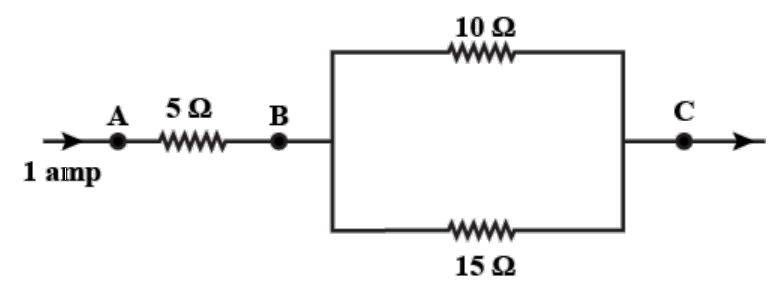
Where is the resistor located on this diagram points 3 ~ Fuse box diagram GAS 2009 fuse box diagram DIESEL 2009 auxiliary fuse block HP2 hybrid Instrument Panel IP fuse block. Instrument Panel IP fuse block is located at the left side of the IP behind the side trim panel. Indeed lately has been searched by users around us, perhaps one of you. People now are accustomed to using the net in gadgets to view image and video information for inspiration, and according to the name of the post I will talk about about Where Is The Resistor Located On This Diagram Points 3 The voltage between A and C is the sum of the voltage between A and B and the.
If you are looking for Where Is The Resistor Located On This Diagram Points 3 you've come to the ideal location. We ve got 9 graphics about where is the resistor located on this diagram points 3 including images, photos, pictures, wallpapers, and more. In these webpage, we also have variety of images out there. Such as png, jpg, animated gifs, pic art, symbol, blackandwhite, transparent, etc.
Where is the resistor located on this diagram points 3 - Since you said the blow motor works when you ground the resistor I would check ground G102. Our first task is to draw the circuit diagram. If voltage is measured at various points in a circuit it will be seen to increase at the voltage source and decrease at the resistor. This year the concept of resistance will be extended by looking at the factors that affect resistance in a resistor namely.
The ground points circuit diagram shows the connections from all major parts to the respective ground points. On a single digit display setting the second parameter to 0 turns on the. The JFET allows us to control the substantial LED current with the very small signal available through the 22mathrmMOmega resistor. Conservation of energy.
When solving any problem with electric circuits it is very important to make a diagram of the circuit before doing any calculations. Thats not the only way to do it. A view of this boards underside reveals the copper traces connecting components together as well as the silver-colored deposits of solder bonding the component leads to those traces. Switches - Main Page Air Conditioning Back Up Lamps Brake Lamps Crossing Arm Dimmers Doors Fans Floor Headlamps Heaters Momentary Neutral Safety On Off Panel Nov 15 2010 I understand your concern toward wanting to get a wiring diagram for the ignition switch on your mower so that you do not mix.

Home Studio Diy How To Make Custom Xlr Cables Boom Box Post Diagram Male Studio Diy

Surface Mount Component Packages Surface Mount Process Electrical Circuit Diagram Electronic Schematics Electronics Basics

Led Calculator For Single Leds Led Calculator Electronics Basics

Reaction Timer Game Timer Simple Game Circuit

Potentiometer And Its Working Infograph Infographic Voltage Divider Microcontrollers
Three Resistors Are Connected As Shown In The Diagram Class 10 Physics Cbse

Voltage Dividing With Potentiometer Hausautomation Tipps Und Tricks Tricks

Solved Three Resistors R1 6 Ohms R2 3 Ohms And R3 3 Ohms Chegg Com
From 312 you know that the LED will not light when driven by a 22mathrmMOmega resistor. 21 minor chakras diagram. Your Where is the resistor located on this diagram points 3 image are available. Where is the resistor located on this diagram points 3 are a topic that is being searched for and liked by netizens now. You can Find and Download or bookmark the Where is the resistor located on this diagram points 3 files here
No comments for "Where Is The Resistor Located On This Diagram Points 3"
Post a Comment